


Home Reed Solomon Project Reed Solomon Galois Fields Theory Reed Solomon LABVIEW Implementation Reed Solomon Experiments
Reed Solomon Coding is an error correction method especially useful for burst errors or contiguous errors in the bit stream as opposed to random bit errors. RS(n,k) can correct up to t symbols where t = 0.5(n-k). Reed Solomon codes are advantageous for burst errors due to the fact that any number of erroneous bits in a given symbol is treated as only one error. Thus, any number of bits errors in up to t symbols can be corrected by the Reed Solomon code. Unlike such contiguous errors across a symbol, when there are random bit errors, t bit errors across t symbols are enough to max out the Reed Solomon code's error correction capacity. Such errors fail to utilize Reed Solomon's burst error correcting capability. To test this characteristic feature of Reed Solomon Code, let us examine two sources of error simulation: AWGN (Additive White Gaussian Noise) Channel and Binary Erasure Channel.
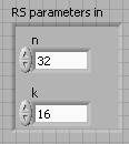
Our project's implementation of RS(32,16) can be tested in both channels: Noise and Erasure channel, using a Simulator created in LabVIEW. The difference in efficiency of the RS code for the two types of errors (burst and random) can be observed. More importantly, the capacity of the Reed Solomon code in correcting burst errors can be examined.
First let us set up the USRP hardware. Next the Transmitter VI (Virtual Instrument) is tested which contains the Reed Solomon Encoder, followed by the Receiver VI which contains the Reed Solomon Decoder. The Receiver VI also displays stats of the RS code implementation. Finally, a Simulator VI is used to mimic random and burst errors for analysis.
Note that in order to run the code, full version of LabVIEW must be installed on the computer. Visit http://www.ni.com/labview/ to download.
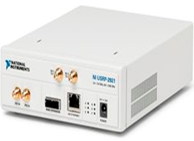
USRP (Universal Software Radio Peripheral) setup
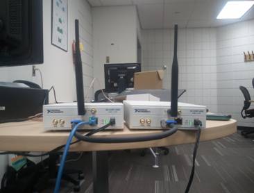
1. Open two USRPs. One of these is the transmitter and the other is the receiver. Power both USRPs to AC outlets. Once powered, green light should be visible blinking next to letters on both USRPs.
2. Attach antennas to both USRPs by plugging its end to pin labeled RX1 TX1 on the USRP.
3. Connect the two USRPs to each other using the MIMO cable plugged into the MIMO Expansion port on both USRPs. With the connection in between the USRPs established, it will be sufficient to connect only one of the USRPs to the computer.
4. Plug one end of an ethernet cable to one of the USRP's GB Ethernet port and the other end of the ethernet cable to the computer. The computer will now be able to access both USRPs with the help of the MIMO cable connection in between the USRPs.
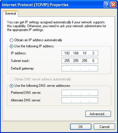
5. To enable wireless communication in between the USRPs and communication with the computer, IP addresses must be set. To do so on a Windows computer: Control Panel > Network Connections > Local Area Connection > Internet Protocol(TCP/IP) > Click radio button "Use the following IP address> Enter IP address 192.168.10.2 and allow Subnet mask to autofill 255.255.255.0. This USRP will serve as your transmitter. Select OK and close out of all the preceding windows.
6. Open NI USRP Configuration Utility (available when LabVIEW is installed on the computer) by searching the start menu. The two devices (USRPs in our case) must have different IP addresses: 192.168.10.2 and 192.168.10.3. If this is not the case, please change.

Launch LabVIEW
Transmitter VI
1. Open top_tx.vi which is the Transmitter VI.
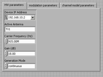
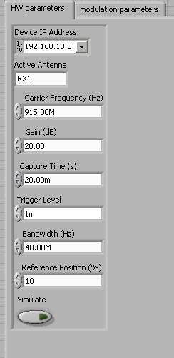
2. On the front panel, the Device IP address must match the transmitter's IP address which in our case is 192.168.10.2
3. Select and make sure of the following parameters in the front panel:
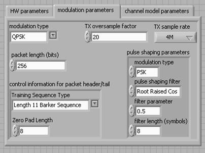
4. Run VI by pressing Ctrl+R or Operate>Run on the menu bar.
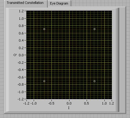
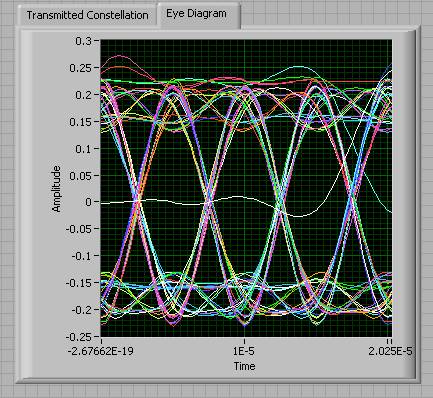
Once Run, the Transmitted Constellation and Eye Diagram displayed the following graphs in our experiment.
Receiver
1. Open top_rx.vi which is the Receiver VI.
2. Change IP address to 192.168.10.3 on the front panel.

4. Run VI by pressing Ctrl+R or Operate>Run on the menu bar.
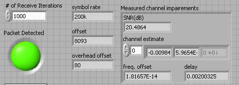
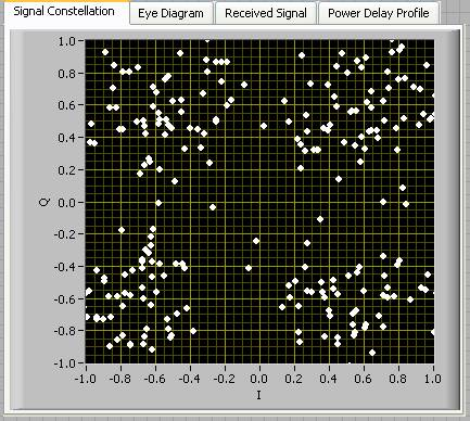
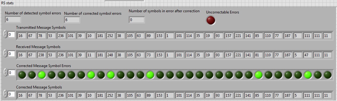
The following Signal Constellation represents the erroneous message received by the Receiver USRP. Note how different it looks from the Transmitted Constellation. Beside are stats accounted by the Receiver VI with the Reed Solomon code implemented.
Experiment: To observe RS error correction scope when implemented for random errors (Noise channel) versus burst errors (Erasure channel).
1. Open rs_simulator.vi.
2. Change packet length to 256. For best results, set to 20 intervals (**) and 1000 iterations. Range start: -14 and Range end: -6.
3. Switch between noise channel and erasure channel by clicking on the button. 
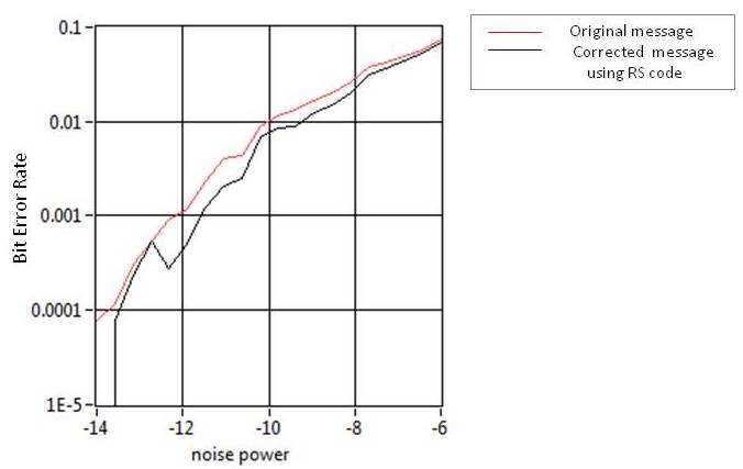
4. First, Reed Solomon code was implemented when data was sent through AWGN Noise Channel. The following figure plots the Bit Error Rate (BER) versus noise power in an AWGN channel using simulation. RS(32,16) is used.
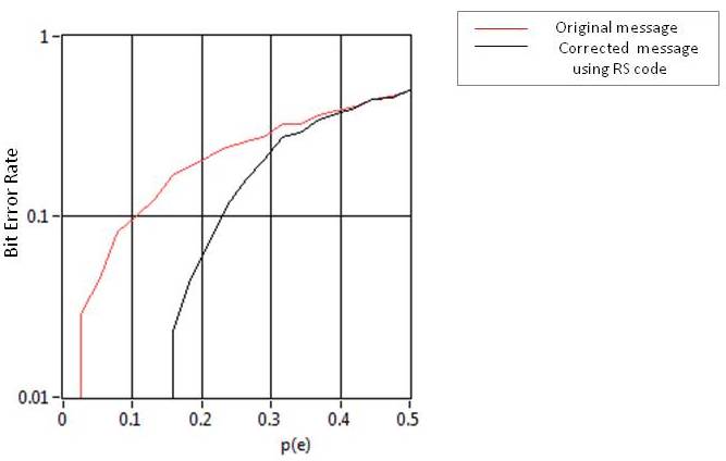
5. Noise power was then switched to p(e) to produce the next graph. The following figure plots the BER versus p(e), the probability of a symbol erasure in a Binary Erasure Channel using simulation. RS(32,16) is used.
Results and Conclusion
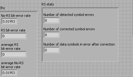
In the first graph, there is not much difference between the original message and the corrected message. When Reed Solomon code is implemented for a message simulated in AWGN channel, no significant improvement is observable. This is as expected because AWGN (noise) channel causes bit errors to occur randomly. This results in limting the RS code by correcting 8 bit errors in 8 symbols. The full potential of Reed Solomon error correction technique is utilized when the message is simulated in the Binary Erasure Channel as seen in the second graph. There is a significant reduction in Bit Error Rate as long as p(e) <0.25. Such an erasure channel results in burst errors or contiguous errors. Reed Solomon code can then correct any number of bits in up to 8 symbols.
In the Binary Erasure Channel performance, the original and corrected message converge when p(e) reaches 0.4. This is because when the probability of a symbol erasure is greater than 0.4, the probability of having more than 8 erroneous symbols in the message converges to 1. Since RS(32,16) can correct only up to 8 symbols, its performance deteriorates when there are greater than 8 erroneos symbols. Following is the equation that gives the probability of having more than 8 errored symbols in a 32 size packet.

Prepared by Amulya Kattimani, a Rutgers ECE undergraduate student